Mfr Part # MMS0293-01
L293D Motor Shield
TAEJIN
License: Apache License, Version 2.0 Arduino
When working on Arduino-based robotics or automation systems, controlling motors efficiently becomes essential. Directly connecting motors to Arduino is not practical due to current limitations, which is why motor driver shields are widely used.
One of the most beginner-friendly and versatile options is the L293D Motor Driver Shield, which allows you to control multiple types of motors using a single board.
In this guide, we will first understand how the L293D shield works and then implement a practical servo motor control setup using Arduino UNO.
The L293D Motor Driver Shield is an expansion board designed to simplify motor interfacing with Arduino. It acts as an intermediary layer between the microcontroller and motors, allowing safe and controlled operation.
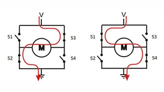
At its core, the shield uses L293D H-bridge motor driver ICs, which enable bidirectional current flow. This makes it possible to control both the direction and speed of motors.
The shield supports:
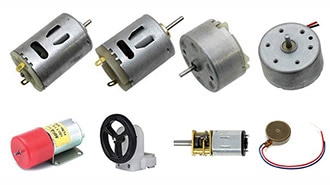
Up to 4 DC motors
Up to 2 stepper motors
Up to 2 servo motors
This makes it suitable for applications like robotic vehicles, automation systems, and motion control projects.
The shield integrates multiple functionalities that simplify hardware design:
Control of four DC motors simultaneously
Support for two stepper motors
Dedicated connectors for two servo motors
Motor voltage range from 4.5V to 24V
Up to 600mA current per channel
Built-in 74HC595 shift register for efficient pin usage
External power input support for motors
Compatible with 5V logic systems
Understanding the internal components of the shield helps in better utilization.
The L293D IC is a dual H-bridge motor driver. It allows current to flow in either direction through a motor, enabling forward and reverse rotation.
Since the shield contains two L293D ICs, it can control multiple motors at once.
This IC is used to reduce the number of Arduino pins required for motor control. Instead of directly using many digital pins, it converts serial data into parallel outputs to control motor directions.
The shield provides flexibility in power supply:
Single supply mode (Arduino powers motors)
External supply mode (recommended for stability)
Two 3-pin headers are available for servo motors:
SERVO_1 → Controlled via PWM pin D10
SERVO_2 → Controlled via PWM pin D9
These headers make servo integration very straightforward.
The shield internally uses several Arduino pins, which is important when designing circuits.
D3, D4, D5, D6, D7, D8, D9, D10, D11, D12
Because of this, very few digital pins remain free, so analog pins are often used as digital inputs.
M1, M2, M3, M4 → DC motors
M1 + M2 → Stepper motor
M3 + M4 → Stepper motor
SERVO_1 → PWM pin D10
SERVO_2 → PWM pin D9
Now, let’s implement a simple project to control an SG90 micro servo motor using the L293D shield.
This example demonstrates how to control servo position and movement direction using buttons and a potentiometer.
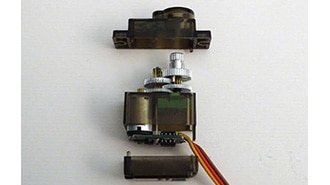
SG90 Servo Motor (5V)
Push Buttons (2)
Arduino IDE
Servo Library (built-in)
LiquidCrystal I2C Library
The motor driver shield should be mounted directly on the Arduino UNO. In diagrams, it may appear separated for clarity.
The potentiometer is used to control the speed of the servo movement.
Middle pin → A0
One side → 5V
Other side → GND
The voltage at A0 varies based on knob position, which is used to control movement behavior.
Since most digital pins are occupied by the shield, analog pins are used as digital inputs:
A1 → Forward movement
A2 → Reverse movement
These buttons control the direction of the servo arm.
The SG90 servo is connected to the shield:
Signal (Orange) → SERVO_1 (D10)
VCC (Red) → 5V
GND (Brown) → GND
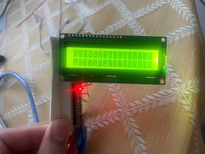
The 16×2 LCD uses I2C communication:
SDA → Arduino SDA
SCL → Arduino SCL
VCC → 5V
GND → GND
When the system powers on, the servo motor initializes to a default center position.
The potentiometer controls the speed or responsiveness of the servo movement by varying the input voltage at pin A0.
Pressing the button connected to A1 rotates the servo in one direction, while pressing A2 rotates it in the opposite direction. The servo continues to move as long as the button is pressed.
Meanwhile, the LCD provides real-time feedback showing movement direction and status.
Servo motors draw current from the Arduino’s 5V regulator, so avoid using high-power servos directly.
Most Arduino digital pins are occupied by the shield, so analog pins are used for input.
Ensure a stable power supply for reliable operation.
/*
Interfacing Micro Servo Motor SG90 with Arduino UNO using L293D motor Driver shield
by www.playwithcircuit.com
*/
#include <Servo.h>
  // Library to run Servo Motor
#include <LiquidCrystal_I2C.h>
  // Library to Run I2C LCD
LiquidCrystal_I2C lcd(0x27, 16, 2);  // Format -> (Address,Columns,Rows )
// Create the servo object connected to SER1
Servo servo;
// Define button pins
const int forwardButtonPin = A1;
const int reverseButtonPin = A2;
// Variable so save current Servo Angle
int servoAngle;
// Define potentiometer pin
const int potPin = A0;
// Read the potentiometer value
int potValue;
// Save motor Speed
int motorSpeed;
// Save previous motor Speed
int previousSpeed;
// counter to clear speed when motor is stopped
int counter = 100;;
void setup() {
  // initialize the lcd
  lcd.init();
  // Turn on the Backlight
  lcd.backlight();
  // Clear the display buffer
  lcd.clear();
  // Set cursor (Column, Row)
  lcd.setCursor(0, 0);
  lcd.print("Servo Motor using");
  lcd.setCursor(0, 1);
  lcd.print("L293D Shield");
  // Set the arm in middle i.e at 90 degree
  servoAngle = 90;
  // Set button pins as inputs
  pinMode(forwardButtonPin, INPUT_PULLUP);
  pinMode(reverseButtonPin, INPUT_PULLUP);
  // Initialize the servo motor, Pin 10 is connected to the PWM pin of Ser1 port of Arduino Shield
  servo.attach(10);
  servo.write(servoAngle); // Set servo to neutral position (90 degrees)
  delay(2000);
  // Clear the display buffer
  lcd.clear();
  // Set cursor (Column, Row)
  lcd.setCursor(0, 0);
  lcd.print("Motor Direction:");
  lcd.setCursor(0, 1);
  lcd.print("Stopped ");
}
void displaySpeed(void){
    // Set cursor (Column, Row)
    lcd.setCursor(9, 1);
    lcd.print("SPD:");
    lcd.print(((motorSpeed*100)/10));
    lcd.print("%  ");
    counter = 0;
}
void loop() {
  // Read the potentiometer value for changing speed as per Analog input
  potValue   = analogRead(potPin);
  motorSpeed = map(potValue, 0, 1023, 0, 10);
  // Read the button states
  bool forwardButtonState = (digitalRead(forwardButtonPin) == LOW);
  bool reverseButtonState = (digitalRead(reverseButtonPin) == LOW);
  // Control the servo motor
  if (forwardButtonState) {
    // Set cursor (Column, Row)
    lcd.setCursor(0, 1);
    lcd.print("Forward ");
    // Increase Servo Angle
    servoAngle+=motorSpeed;
    if(servoAngle>180)
    {
      servoAngle = 180;
    }
    displaySpeed();
  } else if (reverseButtonState) {
    // Set cursor (Column, Row)
    lcd.setCursor(0, 1);
    lcd.print("Backward");
    // Decrease Servo Angle
    servoAngle-=motorSpeed;
    if(servoAngle<0)
    {
      servoAngle = 0;
    }
    displaySpeed();
  }
  else
  {
    if(counter++ > 100)
    {
      lcd.setCursor(0, 1);
      lcd.print("Stopped         ");
      counter = 101;
    }
    else
    {
      // Set cursor (Column, Row)
      lcd.setCursor(0, 1);
      lcd.print("Stopped ");
    }

    if(previousSpeed != motorSpeed)
    {
      displaySpeed();
      previousSpeed = motorSpeed;
    }
  }
  servo.write(servoAngle); // Adjust as needed for your servo's forward position
}This project demonstrates how easy it is to control a servo motor using the L293D motor driver shield with Arduino. The shield significantly reduces wiring complexity and allows multiple motor types to be integrated into a single system.
However, this is just one part of what the L293D shield can do.