Visuino - Controlling Speed - High Torque NEMA 17 Stepper Motor + DRV882
2026-04-17 | By Ron Cutts
License: GNU Lesser General Public License Microcontrollers Motors PWM Serial / UART Stepper Arduino ESP32
In this tutorial, we will use a stepper driver DRV8825, an LED, buttons, resistors, a NEMA17 stepper motor, an Arduino Uno, and Visuino to start/stop and control the speed of the stepper motor.
Watch a demonstration video.
What You Will Need
Arduino UNO (can be any other Arduino)
Breadboard (or breadboard shield)
Green LED (or any other color)
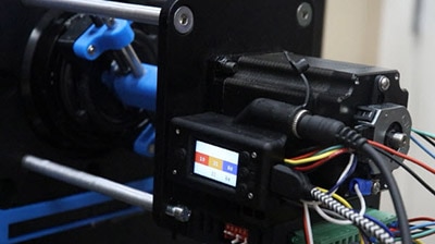
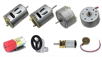
NEMA17 stepper motor (or any other bipolar stepper motor)
Visuino program: Download Visuino


The Circuit
The connections are pretty easy; see the above image with the breadboard circuit schematic.
Connect GND from Arduino to the breadboard pin(-)
Connect 5V from Arduino to the breadboard pin(+)
Connect + on breadboard to resistor1
Connect resistor1 to button1
Connect button1 to Arduino pin (A0)
Connect + on breadboard to resistor2
Connect resistor2 to button2
Connect button2 to Arduino digital pin (2)
Connect + on breadboard to resistor3
Connect resistor3 to button3
Connect button3 to Arduino digital pin (3)
Connect + on breadboard to resistor4
Connect resistor to LED(+)
Connect LED(-) to breadboard pin(-)
Connect driver DRV8825 pin(GND) to breadboard pin(-)
Connect driver DRV8825 pin(STEP) to arduino digital pin(8)
Connect driver DRV8825 pin(reset)and pin(SLEEP) to breadboard pin(+)
Connect motor power supply (+) to driver DRV8825 pin(VMOT)
Connect motor power supply (-) to driver DRV8825 pin(GND)
Connect capacitor pin(+)to driver DRV8825 pin(VMOT)
Connect capacitor pin(+)to driver DRV8825 pin(GND)
Connect 4wires from stepper motors to DRV8825 pin(B2,B1,A1,A2)

Start Visuino, and select the Arduino UNO board type.
To start programming the Arduino, you will need to have the Arduino IDE installed from here: http://www.arduino.cc/
Please be aware that there are some critical bugs in Arduino IDE 1.6.6. Make sure that you install 1.6.7 or higher; otherwise, this will not work! If you have not done so, follow the steps to set up the Arduino IDE to program the ESP8266! The Visuino: https://www.visuino.eu also needs to be installed. Start Visuino as shown in the first picture. Click on the "Tools" button on the Arduino component (Picture 1) in Visuino. When the dialog appears, select "Arduino UNO" as shown in Picture 2


Add Components in Visuino
Add Pulse Generator, set frequency to 0
Add Logic gate AND component
Add 2x Clock generator component
Add UP DOWN counter component
Add Detect Edge component
Add Button component
Add FlipFlop component
Add Inverter component

In Visuino: Connecting Components
Connect Button1 component pin[In] to Arduino Analog Out pin[0]
Connect Button1 component pin[Out] to DetectEdge1 pin [in]
Connect DetectEdge1 pin [Out] to FlipFlop1 pin [clock]
Connect FlipFlop1 pin[Out] to Inverter1 pin [in]
Connect Inverter component pin[Out] to Arduino Digital Out pin[6]
Connect FlipFlop1 pin[Out] to Arduino Digital Out pin[7]
Connect FlipFlop1 pin[Out] to Arduino Digital Out pin[0]
Connect AND1 pin[Out] to Arduino Digital Out pin[8]
Connect AND1 pin[1] to Pulse generator pin[Out]
Select Pulse generator1, on the left in editior select "frequency" editor, click PIN icon and select FloatSinkPin, a new PIN will be shown on Pulse Generator [in]
Connect Pulse generator pin [in] to UP DOWN counter pin [out]
Select Clock generator1, on the left in editior select "enabled" editor, click PIN icon and select BooleanSinkPin, a new PIN will be shown on Pulse Generator [Enabled]
Do the same for Clock generator2
Connect ClockGenerator1 pin[enabled] to Arduino Digital /Out pin[2]
Connect ClockGenerator2 pin[enabled] to Arduino Digital /Out pin[3]
Connect ClockGenerator1 pin[Out] to UpDown counter pin[up]
Connect ClockGenerator2 pin[Out] to UpDown counter pin[down]


Generate, Compile, and Upload the Arduino Code
In Visuino, at the bottom, click on the "Build" tab, make sure the correct port is selected, then click on the "Compile/Build and Upload" button.

Play
If you power the Arduino UNO module, the motor will start humming, and if you click button 1, a green light should light (ready). Now, just click on the right button to increase the steps so that the motor will start spinning, and the second button to lower the speed; see the video.
Congratulations! You have completed your project with Visuino. Also attached is the Visuino project that I created for this. You can download and open it in Visuino: https://www.visuino.eu